GIS Software Elshayal Smart Map Editor 17.001 Free Download
https://drive.google.com/file/d/0B2qR4wxKKE_VUmR6V2hYRHRqb2c/view?usp=sharing
It is a GIS Stand alone desktop application that allow the users to do the following functions
- Map Editing and Digitizing
- Convert GIS Shape to AutoCAD DXF File and Vise versa
- Building Tin Surface Analysis
- Building Contour Surface Analysis
- Converting 2D to 3D Surface Analysis
- Calculating 2D and 3D Areas and Volumes
- Convert Vector and Raster Layer Coordinates System between UTM and Geographic Lon-Lat
- Save layout images with written Lon and Lat coordinates to help exporting them to AutoCAD
- Download and save Google Earth Images as rectified images with world file format .jgw
- Makes Google Earth as a Background of your GIS Geographic Lon-Lat Map
- Convert and use all Transverse Mercator Projections & Transformations
- Convert Shape files to IIS Server GIS Web and Mobile Application with Label and Data Base Search
For Free Download :-
Version 17.001 to Convert GIS Shape files to HTML Google Map Web Mapping and Mobile Application with Label and Data Base Search
https://drive.google.com/file/d/0B2qR4wxKKE_VUmR6V2hYRHRqb2c/view?usp=sharing
OR
http://download.cnet.com/Elshayal-Smart-GIS-Map-Editor/3000-18496_4-10922171.html
OR
http://www.softpedia.com/get/Science-CAD/Elshayal-Smart.shtml
Spatial Digitizing and Editing
A) Building New Shape File Spatial and Data Structure
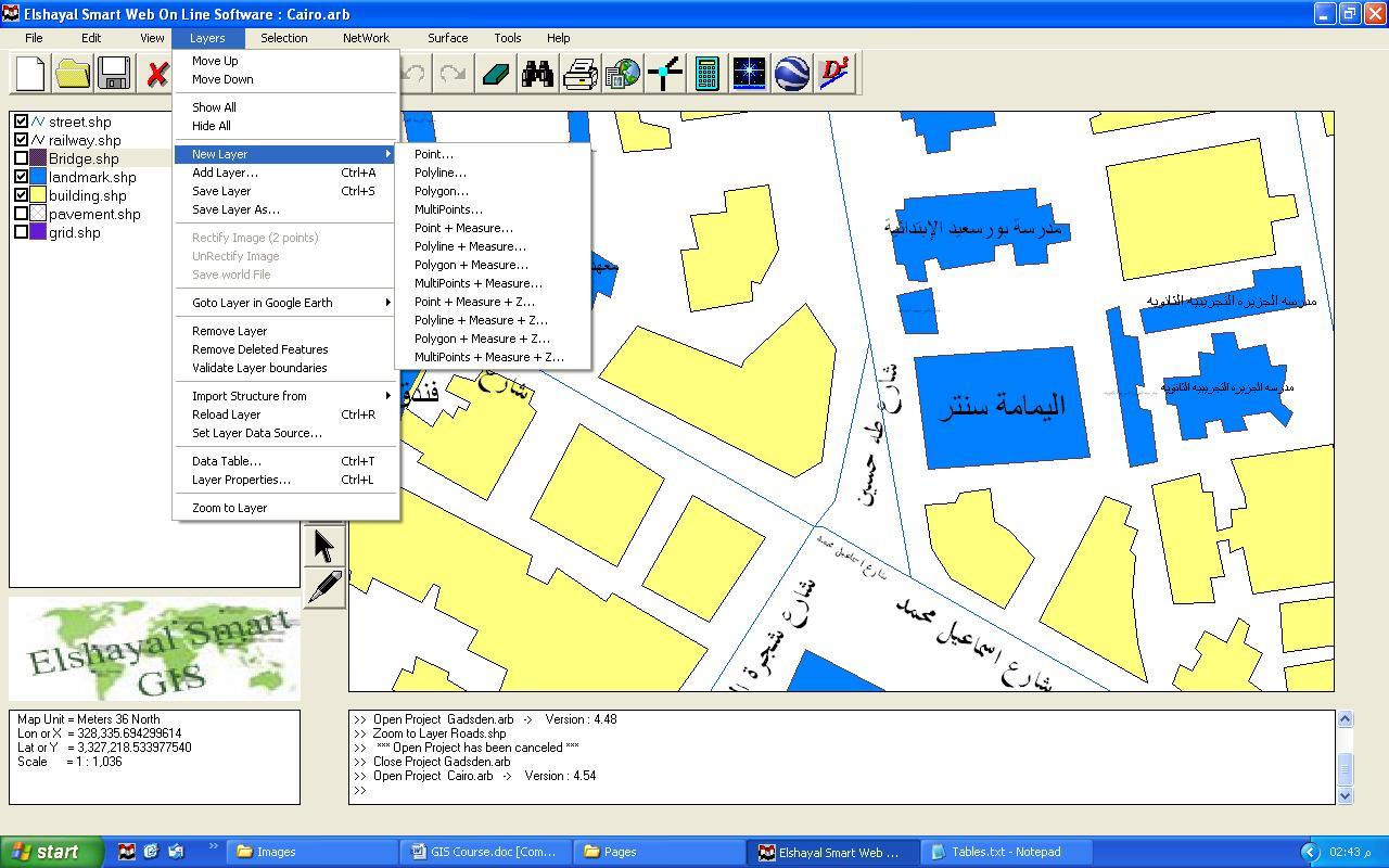
Building New Spatial Shape File
Menu → Layers → New Layer → Select Layer type
Move up, Moves the selected layer up
Move Down, moves the selected layer down
Show all Layers
Hide all Layers
New Layer, Build a new Layer
Add Layer, add an existing layer on the map viewer
Save Layer
Save Layer as, save the layer with different name
Rectify Image (2 points)
Un Rectify Image
Validate Layer boundaries
Go to Layer in Google Earth
Remove layer
Remove deleted features
Import structure from
Reload Layer
Set Layer Data Source
Data Table
Layer Properties
Zoom to Layer
B) Digitizing Spatial Shape File ( Feature – Part – Vertex )
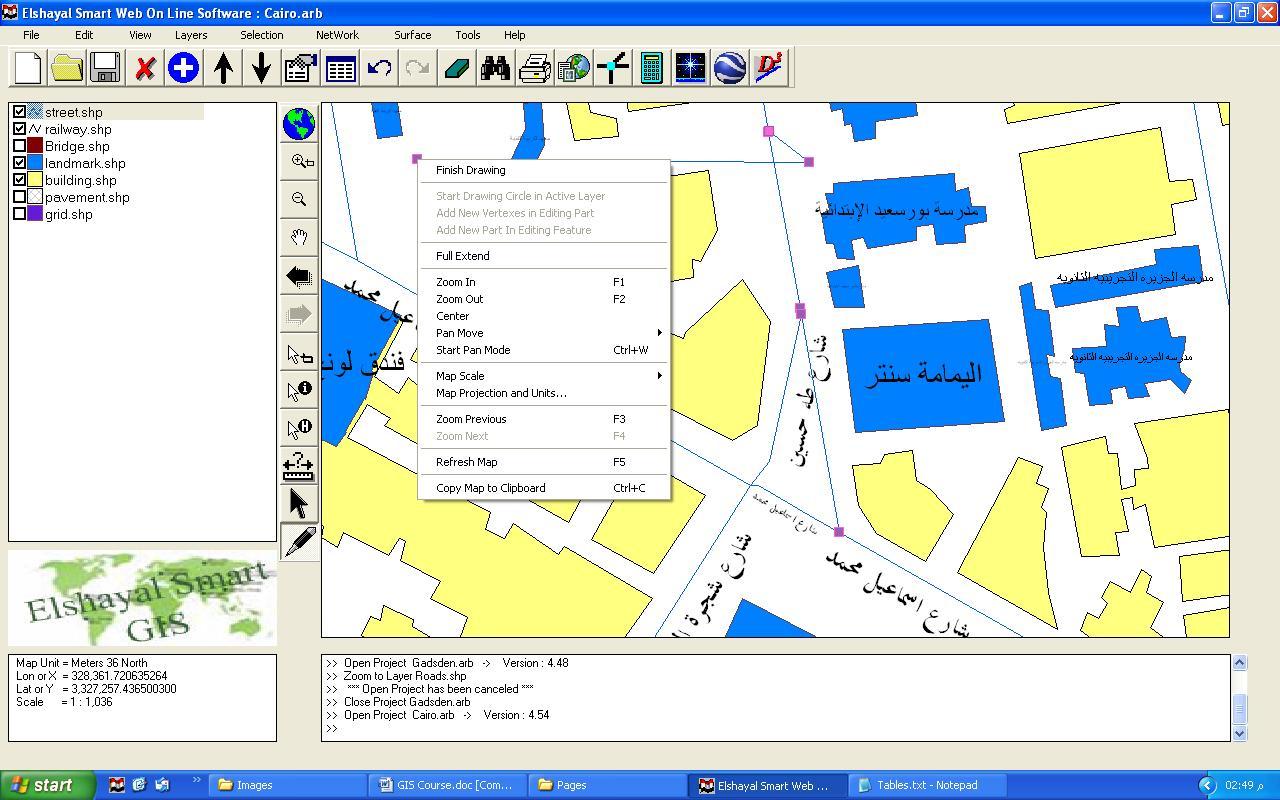
Digitizing Spatial Shape file
Buttons → Add New Feature → Start Digitizing
Finish Drawing
Start Drawing Circle in Active Layer
Add New Vertex in Editing Part
Add New Part in Editing Feature
Full extend
Zoom in
Zoom out
Center
Pan move
Start Pan mode
Map Scale
Map Projection and Unit
Zoom Previous
Zoom Next
Refresh map
Copy Map to Clipboard
C) Editing Shape File ( Feature – Part – Vertex )
Editing Spatial Shape file
Buttons → Edit Feature → Click cursor on the Feature → Right Click
Undo Drawing Map
Redo Drawing Map
Insert Vertex
Delete Vertex
Delete Part
Delete Feature
Divide Feature
Combine Feature
Edit Feature Data
Move Distance
Move to X , Y
Move Settings
Set Pivot Point
Rotate – Scale
Rotate – Scale menu
Go to Feature in Google Earth
Bring Part to Front
Send Part to Back
Invert part Direction
Add New Vertex in Editing Part
Add New Part in Editing Feature
Length
Area
Stop Edit
D) Move Settings
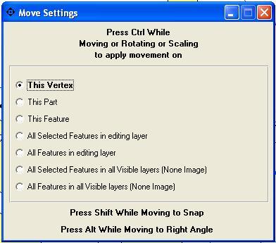
Editing Spatial Shape file
Menu → Layers → Move Settings
Press Ctrl while moving or Rotating or Scaling to apply movement on
This Vertex
This Part
This Feature
All Selected Features in Editing Layer
All Features in Editing Layer
All Selected Features in All Visible Layers (None Image)
All Features in All Visible Layers (None Images)
Press Shift while Moving to Snap or Press Alt while Moving to Right Angle
E) Map View

Menu → View
F) Converting between Shape File types 2D & 3D (Point – Polyline – Polygon)
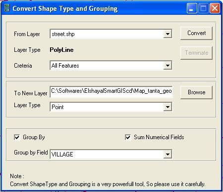
Converting Shape Type and Grouping
Menu → Tools → Convert Shape Type and Grouping
Select Destination Layer
Select Criteria (All Feature or Inside Selected Features or Outside Selected Features)
Select Output Shape File
Select Output Shape File Type
Select Group By or Not
Select Summing Numerical Fields or Not
Select Group By Field
G) Layer Properties
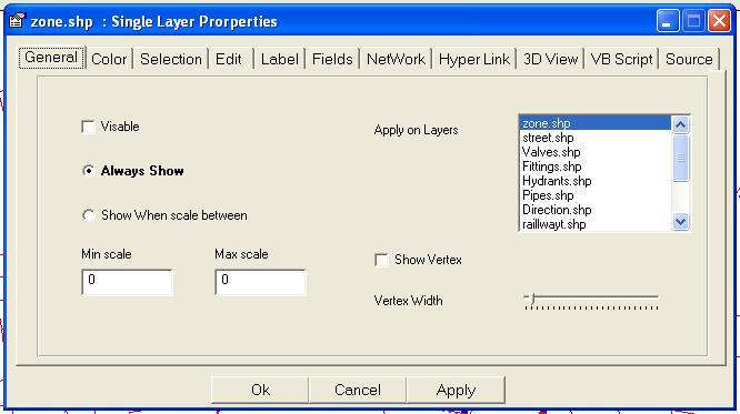
Layer Properties General Option
Menu → Layers → Layer Properties → General
Select Visible or not
Select on which Layers, your selection will be applied
Select Show Vertex or Not
Select Vertex Width
Select Always show to view the layer all the time
Select Show When Scale between Min Scale and Max Scale
Layer Properties Color Option
Menu → Layers → Layer Properties → Color
Select Draw Fore Color and Draw Fill Color
Select Draw Mode
Select Draw Style
Select Draw Width
Select Draw Fill Style
Select Thematic Field and add Values and select each Value Colors, Mode, Style
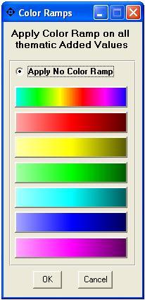
Select Apply Color Ramp to change colors of all added values
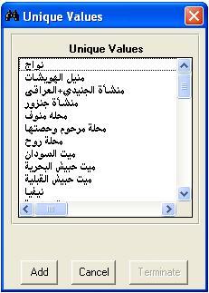
Layer Properties Color Option : Add Thematic Value
Menu → Layers → Layer Properties → Color → Add
Layer Properties Color Option : Apply Color Ramp on Added Value
Menu → Layers → Layer Properties → Color → Apply Color Ramp
Layer Properties Selection Option
Menu → Layers → Layer Properties → Selection
Select Selection Fore Color
Select Selection Fill Color
Select Selection Mode
Select Selection Style
Select Selection Width
Select Selection Fill Style
Select Selectable ( Snap to ) or Not
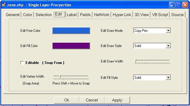
Layer Properties Edit Option
Menu → Layers → Layer Properties → Edit
Layer Properties Label Option
Menu → Layers → Layer Properties → Label
Select Show Label or Not
Select Label Field Name
Select Label Font
Select Label Fore Color
Select Always show to view the layer all the time
Select Show When Scale between Min Scale and Max Scale
Select Refer Label Font Size to this Map Scale
Select Force Label Size to Fit Polyline length and polygon width
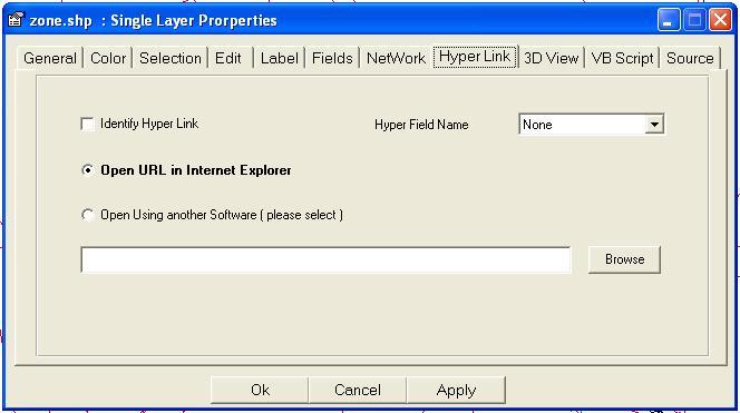
Layer Properties Hyperlink Option
Menu → Layers → Layer Properties → Label
Select Identify Hyperlink or Not
Select Hyperlink Field Name
Select Open URL in Internet Explorer
Select Open Using another Software (Please Select)
Attribute Data Table
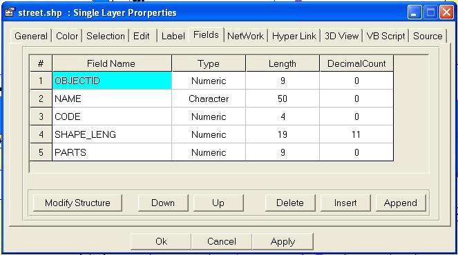
A) Modifying Dbf File Data Structure
Layer Properties Fields Option
Menu → Layers → Layer Properties → Fields
Press Append Button to add new field at end of fields list
Press Insert Button to add new field above of the selected Field
Press Delete Button to delete the selected field
Press Up Button to move Selected Field Up
Press Down Button to move Selected field Down
In the Field Name Columns, type a Unique Field Name
In the Type Columns, Select ( Character or Date or Logic or Numeric )
In the length Columns, Enter the field Length
In the Decimal Count Columns, Enter the number of Decimal digits
Press Modify Structure Button to apply the Field Modification
B) Editing Data Table
Editing Data Table
Menu → Layers → Data Table
Undo Data Edit
Redo Data Edit
Select Features
Unselect Features
Delete Features
Undelete Features
Edit Feature Data
Cut Cells
Copy Cells
Past Cells
Fill Past
Fill Series
Clear Cells
Sort Rows Ascending
Sort Rows Descending
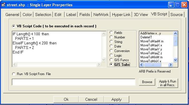
C) Running VB script in Data Table Fields
Layer Properties VB Script Option
Menu → Layers → Layer Properties → VB Script
Select Fields for Fields Name List
Select Number for VB Number Functions List
Select String for VB String Functions List
Select Date for VB Date Functions List
Select Conversion for VB Conversion Functions List
Select Logic for VB Logic Functions List
Select GIS Funcs for GIS Functions List
Select GIS Subs for GIS Procedures List
Press Apply & Run in All records
Note that "ARB" Prefix is Reserved
Select Run VB Script from File (to Load and Run External VB Script file)
D) Editing One Feature (Record)
Edit Feature
Menu → Edit → Edit Feature Data